The Datalink Service Load Balancing(DSLB), also known as Uplinks Load Balancing, allows the creation of highly available and scalable WAN Uplinks at layer 3 protocol.
The DSLB farm profile allows users to create route-based farms where the backends are uplink routers or gateways. This farm profile is usually ready to share several uplink WAN router access using the load balancer as an uplink channel multiplexer (1 input and several router line outputs). Therefore, DSLB farms can be used as highly available communication links, and can also be used as bandwidth scaling, increasing the bandwidth between the router’s backend links.
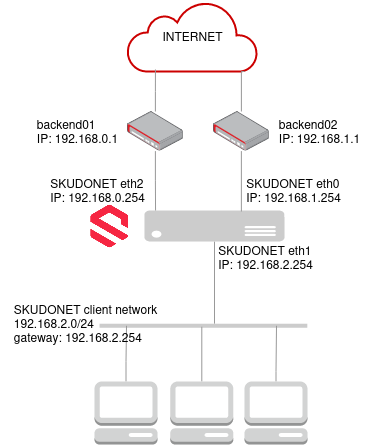
The scheme below shows an example of load balancing several uplinks with different weights.
- DSLB farm is configured using Virtual IP 192.168.2.254 (eth1).
- This IP is used as the default gateway for the client network 192.168.2.0/24.
- DSLB farm is configured with two IP backends 192.168.0.1 and 192.168.1.1
- 192.168.0.1 and 192.168.1.1 are the local IPs of the backends (internet providers). Each router has its public IP which reaches public networks.
- if backend01 or backend02 fails the DSLB farm detects the failure and moves the traffic through the other available backend (internet provider)
- SKUDONET requires to be configured in each network where the local IP of the internet provider is present (eth0 and eth2)
DSLB Farms List
Consider using the following action buttons for each selected farm.
Create Farm. Creates a new farm managed by the DSLB farm profile.
Restart. Reboots a farm service in the DSLB farm profile.
Stop. This action stops the selected farm’s services.
Start. This action starts the selected farm’s services.
Delete. This action stops the services and deletes the farm’s configuration.
The actions will be executed in batches in all the selected farms (You may use the multichoice selector checkbox).
DSLB Farms Table
Farm listings and properties of each farm. The fields shown per farm are described below.
Name. A descriptive name of a farm. This value will be unique in all the virtual services you create.
Virtual IP. The IP address which is managing the incoming local traffic. This virtual IP could be moved to another node of the cluster and could behave as the LAN default gateway.
Interface. The network interface that is managing the incoming traffic and shares the requests with the WAN networks.
Status. The status of a given farm. These are the available indicators.
 Green. Means UP. The farm is running and all backends are UP.
 Red. Means DOWN. The farm is stopped.
 Yellow. Means RESTART NEEDED. There are recent changes that need a farm restart to be applied.
 Black. Means CRITICAL. The farm is UP but there is no backend available or they are in maintenance mode
 Blue. Means PROBLEM. The farm is running but at least one backend is down.
 Orange. Means MAINTENANCE. The farm is running but at least one backend is in maintenance mode.
Actions. These are the available actions/icons for every farm in the table:
- Edit. Changes the basic and advanced options for a virtual service or a farm, create new services, and applies those changes to the backends.
- Restart. The Farm will reboot.
- Stop. This action is only available if the farm is running. All the traffic managed by this farm will be dropped once the command is executed.
- Start. This action is only available if the farm is stopped. The service will bind to the configured IP and interface, and hence the traffic through them will be handled by the farm.
- Delete. The Farm will be stopped and all the configuration files deleted. The IP will be released so it could be used by another farm.
Next step, create a DLSB farm.


